Pregiati strumenti di misura per il controllo di qualità nella sala metrologica e nei reparti di produzione, accettazione merci o sviluppo.
Gear Metering Pumps & Meter Mix Dispense Machines with highest accuracy for processing liquids and pastes.
High-precision rotary stroke bearings for backlash-free linear and rotational movements for use in machine and device construction.


Metrologia innovativa per un'ampia gamma di applicazioni:
- • Lunghezza e diametro
- • Superficie e contorno
- • Forma e posizione
- • Ingranaggi e alberi

Precise mixing and metering of liquids and pastes:
- • Gear metering pumps
- • Pumps for fiber production
- • Meter mix dispense machines as well as mixing heads

Rotary stroke bearings for backlash-free linear and rotary movements in:
- • Mechanical engineering
- • Precision engineering
- • Optik
- • Electronics
- • and many other industries


As an internationally active company, Mahr holds its patents not only in Germany, but worldwide.

Shape measurement: understanding common problems
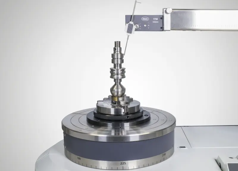
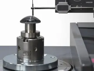
In the simplest case, shape measurement involves a probe and probe arm with sensing element. This is moved along an ideal circular or linear path to collect data on probe movements relative to this ideal geometry. The analysis is usually quite straightforward: the measured data points are filtered and mathematical operations are performed on them to determine the results. Although it is one of the most basic measurements used to support many manufacturing processes, some steps are often performed incorrectly. Particularly common errors occur in the choice of filter and probe element.
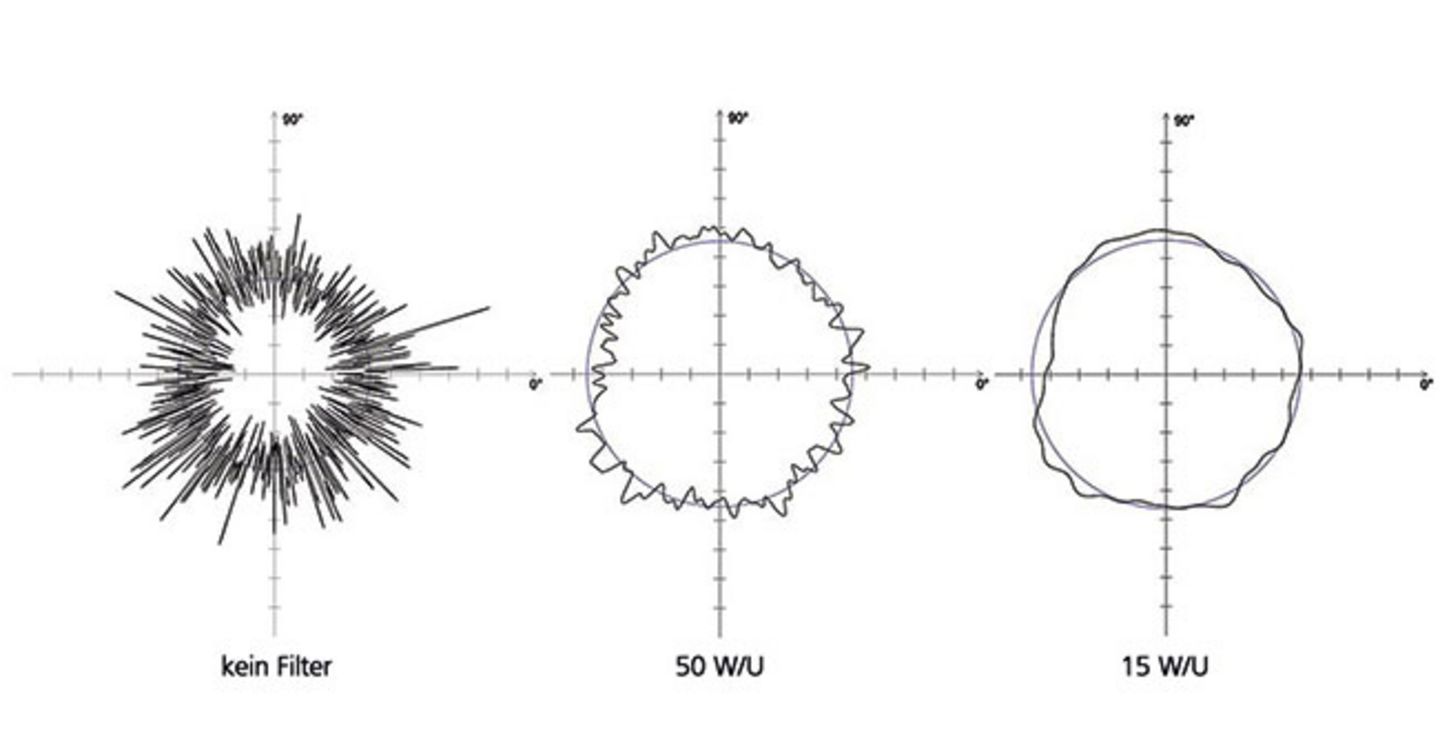
Use of incorrect filters Historically, 50 W/U was assumed to be the standard value for roundness measurements. While this filter may be suitable for many applications, it is not suitable for all. The new DIN EN ISO 1101:2017-09 makes it possible to specify a suitable filter setting directly with each shape tolerance in the drawing. Nevertheless, it is still true that the correct choice of filter must be based on the measurement task. It is the responsibility of design, work planning and quality management to specify requirement-related filter settings, to record these in in-house standards and to prescribe them for all internal and external suppliers.
Realistically, form measurement is a process for measuring form deviations. Traditionally, it is carried out in air-conditioned laboratories by highly qualified specialists, but nowadays it is often performed directly on the shop floor by employees entrusted with a wide range of tasks. Whether measuring form or roughness, the procedure is essentially the same. For any given surface measurement, many sample points are typically used to represent the entire surface. These points are then filtered to obtain only the desired data. For example, in surface roughness testing, the shorter wavelength data is retained for analysis, while the shape-related data is discarded because this information is not needed. In contrast, when measuring shape, the short wavelength data is filtered out so that the long wavelength data representing shape can be measured. This is the first point of error for many users: The subtle nuances of filtering are not always readily understood and therefore the wrong filters are often chosen.
Shape measurement filters are confusing to many metrologists. For example, when discussing surface roughness measurement, filter settings are referred to in terms of millimeters or inches. When the filter is set to 0.8 mm, it is generally understood that surface deviations of less than 0.8 mm are considered surface roughness, while elements greater than 0.8 mm are considered surface shape defects.
Shape filters for roundness measurements, however, are usually specified in terms of angular size - rather than length or distance. To make things even more confusing, the specification does not state it directly in angular degrees, but in a unit known as 'waves per revolution' or W/U (UPR). Many users choose 50 W/U as a typical default value. This means that the length of the filter is 1/50th of a circle - or 7.2 degrees.
Consider workpiece diameter for filter selection However, the arc length corresponding to 7.2 degrees on the surface of a round object changes with the diameter (d) of the object. A simple formula for the circumference of a cylinder is: π * d. So a cylinder with a diameter of 4 mm would have a circumference of 12.57 mm - and therefore 7.2 degrees would cut out an arc length that measures 0.25 mm along the surface. If, on the other hand, a cylinder with a diameter of 20 mm is to be measured, it would have a circumference of 62.83 mm, and the 7.2 degrees would correspond to an arc length of 1.26 mm. Thus, if the same 50 W/U filter setting is maintained on the gauge, five times greater surface deviations will be considered as the boundary between the shape and surface roughness characteristics in the case of the larger part. On virtually all gages, the filter setting can be changed simply by clicking a button in the software - but many do not understand the meaning of W/U (UPR) and therefore do not change the default settings.
The opposite is also sometimes true: lacking an understanding that the filter setting has a significant impact on what is filtered out of the data or retained for analysis, metrologists may be tempted to choose a different setting. However, a different value would alter the results, leading to a result that "looks better" but is not truly correct for the size of the DUT. The bottom line is that the filter should be set correctly for the particular DUT.
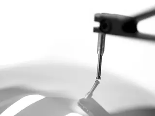
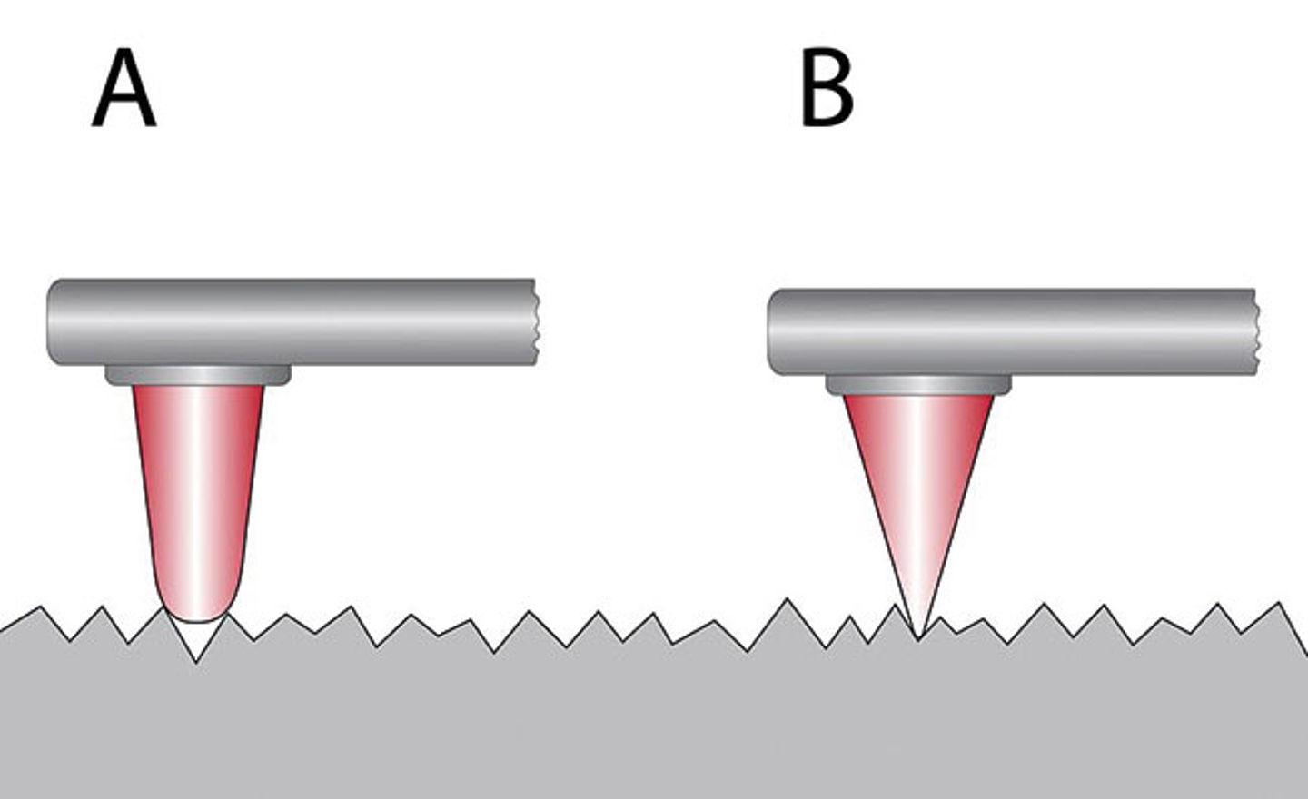
Incorrect Stylus Size A second common mistake is that users rely on a single stylus size to measure all parts, regardless of the size of the DUT. In fact, the stylus ball itself represents a mechanical filter that should be selected according to the part size and the maximum number of waves per revolution that can be measured.
The example of a small component with a diameter of 4 mm can be used to illustrate the problem: If the measuring surface is scanned using a probe with a probe element that is too large, it cannot run well along the surface and precisely follow the ups and downs of the peaks and valleys. If probing elements are used on a probe that approximates the size of the workpiece diameter itself, it becomes very difficult to get a good evaluation of the surface. In this case, the use of this probe element causes a mechanical filtering - even before any mathematical filtering is done. VDI/VDE 2631 Sheet 3 provides the user with a guide to selecting the correct sensing element based on the W/U settings, the maximum expected single-wave depth and the test specimen diameter.
Conclusion Although shape measurement is one of the basic tasks supporting many manufacturing processes, many users often perform some aspects of it incorrectly. This can affect both the quality of the measurements and the overall quality of the final product. By following some basic steps, such as correctly applying the most appropriate filters for the situation and determining the correct data for the application, accurate results can be ensured. Using the best-fitting accessories, such as probe balls sized precisely for the application, also takes the user a long way toward improved measurement data quality - and ultimately higher workpiece quality.