High-quality metrology for quality control in the measuring room, production, incoming goods and development.
Gear Metering Pumps & Meter Mix Dispense Machines with highest accuracy for processing liquids and pastes.
High-precision rotary stroke bearings for backlash-free linear and rotational movements for use in machine and device construction.


Innovative metrology for a wide range of applications:
- • Length and diameter
- • Surface and contour
- • Form and position
- • Gears and shafts

Precise mixing and metering of liquids and pastes:
- • Gear metering pumps
- • Pumps for fiber production
- • Meter mix dispense machines as well as mixing heads

Rotary stroke bearings for backlash-free linear and rotary movements in:
- • Mechanical engineering
- • Precision engineering
- • Optik
- • Electronics
- • and many other industries


As an internationally active company, Mahr holds its patents not only in Germany, but worldwide.

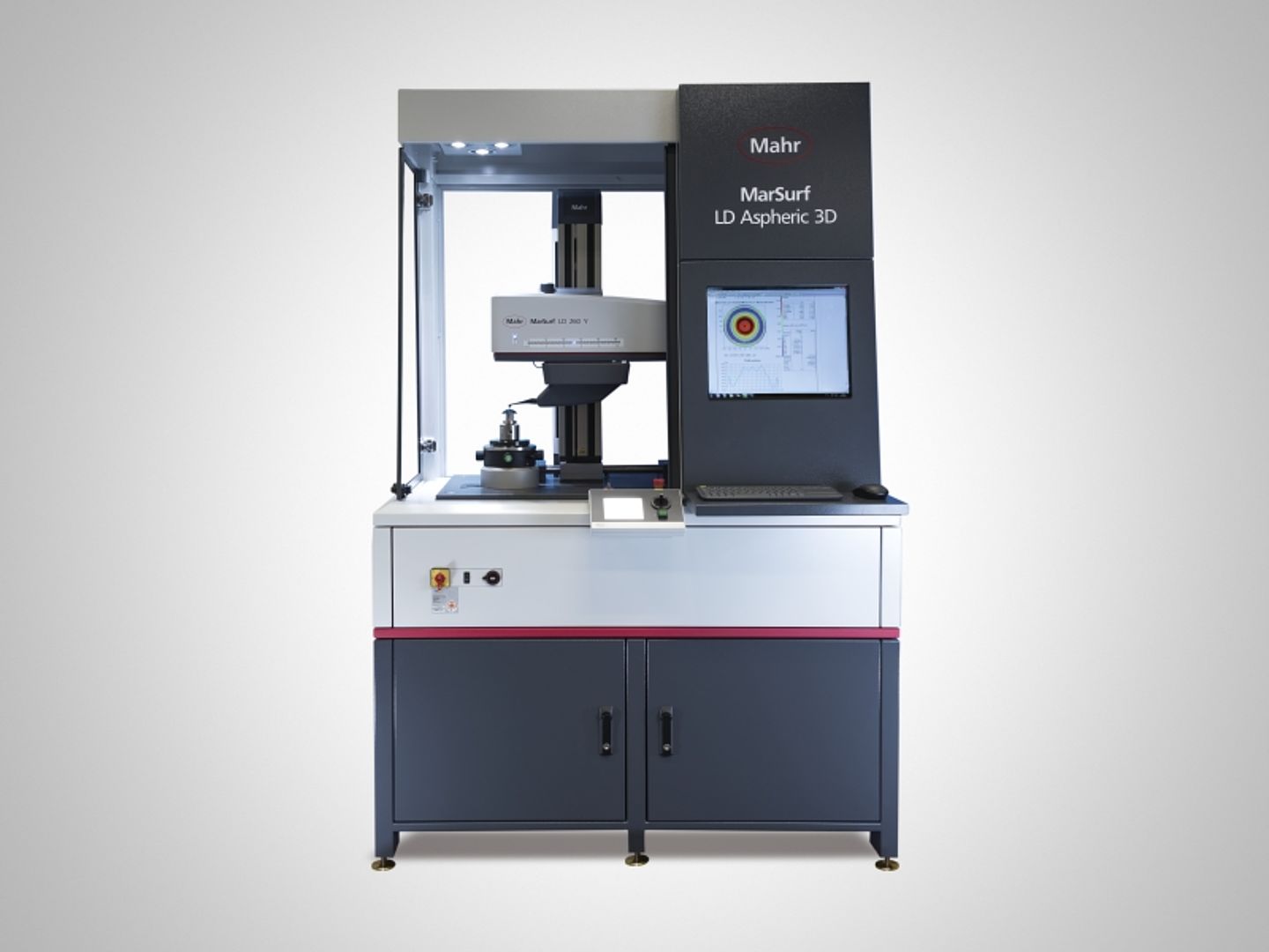
Testing double-sided optical elements with the MarSurf LD 260 Aspheric 3D

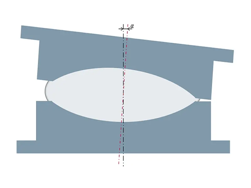
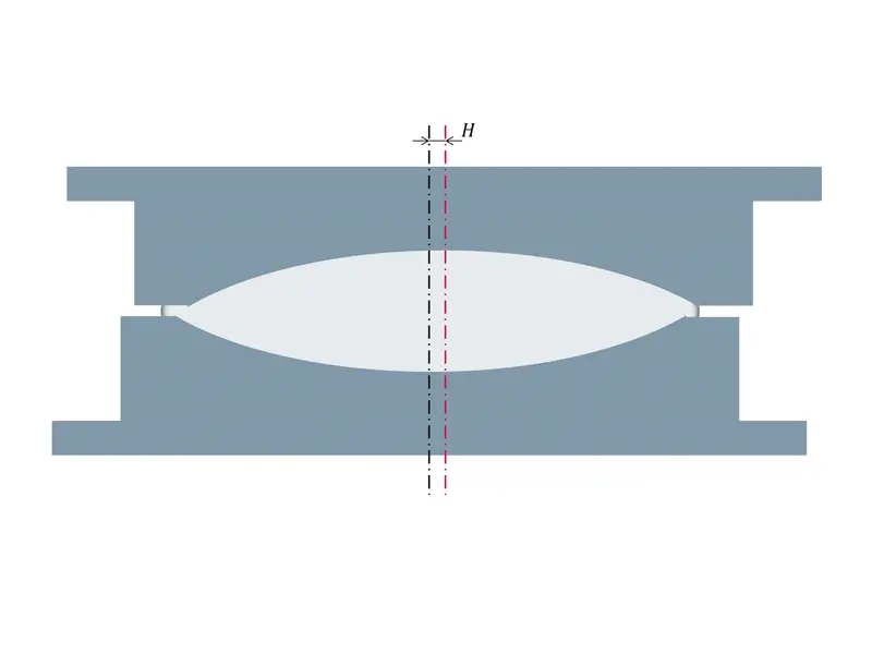
Two factors are essential for precise production: on the one hand, the accuracy of the negative geometry that is brought into each mold half of the intended optical functional surface and on the other hand, the alignment of the two mold halves to each other. Any alignment errors of an optical lens manufactured in this manner result in a faulty position of the two opposing optical functional surfaces of the lens. However, the alignment of the two tool halves to each other can only be detected on the manufactured workpiece, the optical element. In optical production, manufacturing errors such as tilting and lateral offset are a general problem. The centering errors and their tolerances are precisely defined in DIN ISO 10110 Part 6.
Error potential during alignment and centering
In order to be able to determine the alignment of the optical axes of the two halves of the tool to one another before production, a third geometry, such as the cylinder edge, for example, is often used as a reference. The information about the optical axes of the individual optical surfaces is the basic requirement for being able to determine tilting and lateral offset (decentration). In contrast to spherical or planar optical surfaces, a bi-aspheric optical element already has two clearly defined optical axes from the two aspheric geometries themselves. Therefore, tolerancing of the tilt and the lateral offset to a third, external reference in the case of a bi-asphere is not necessary. The challenge is to find a metrological solution to capture the orientation of both optical surfaces in direct relation to each other. Not only can one draw conclusions about the quality of the produced lens, but also optimize the tools for the manufacturing process.
Measurement with double probe tip as a solution
Due to the increasing high metrological requirements for optical elements, Mahr application engineers have developed a measuring method, which allows a new approach to both the tolerability as well as the optical design. With this method, all relevant values can be recorded in one measurement, without having to resort to external references.
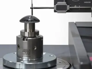
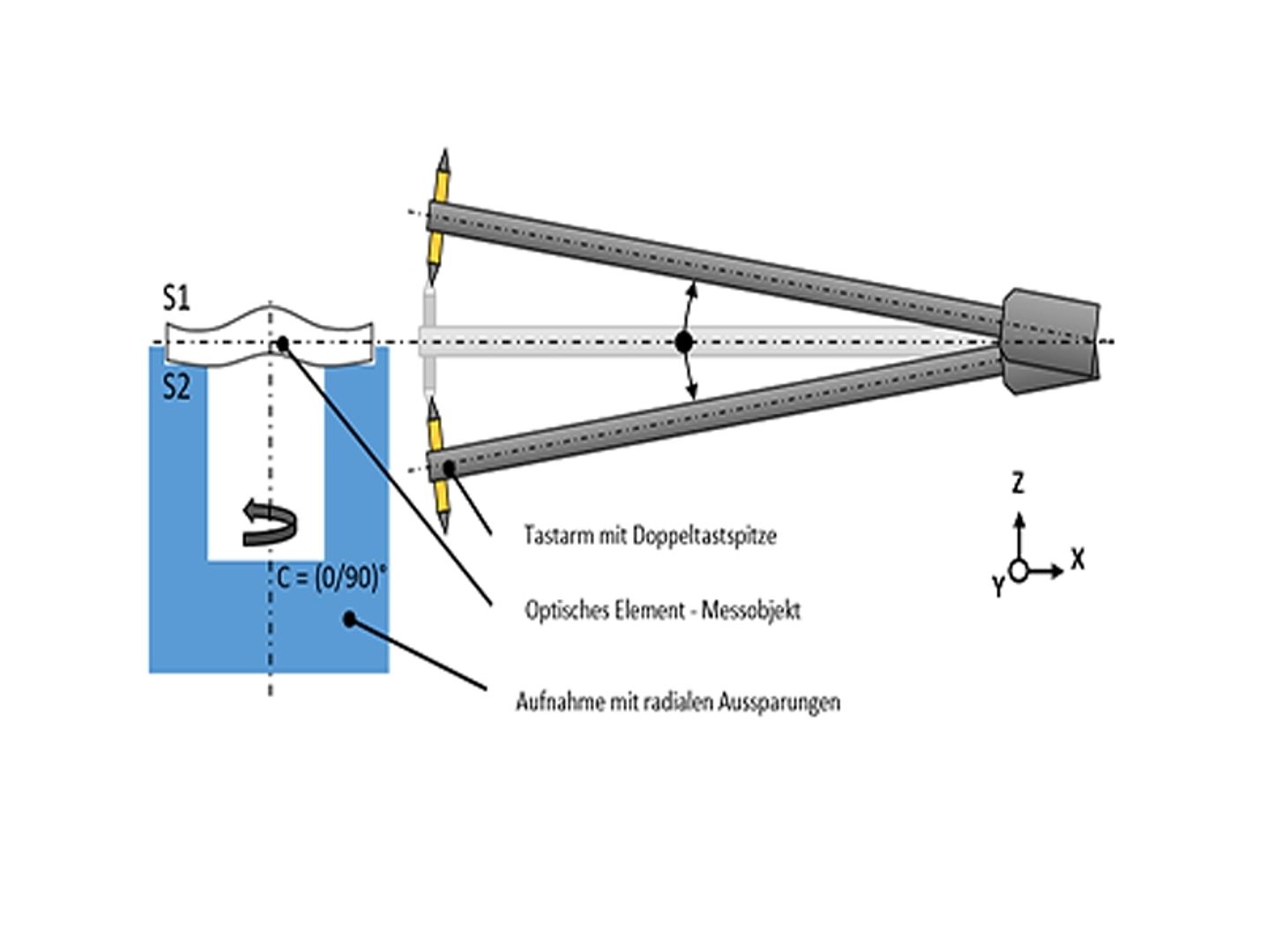
This solution was realized with the surface measuring device MarSurf LD 260 Aspheric 3D. The optical element, e.g. a bi-asphere, is supported by special receptacle with radial recesses. Via a probe arm with a double probe tip, measuring points can be recorded and evaluated on the optical element in parallel or polar offset. In the case of a bi-asphere, for example, this could be achieved with two measurements over the zenith of the optical functional surfaces at 0° and 90°. The measuring positions can be specified in the software and run automatically for subsequent measurements together with the associated evaluation.
MarSurf LD 260 Aspheric 3D
The evaluation options are versatile and can be adapted to the needs of the individual. Typical evaluations on a bi-asphere include:
- Evaluation of the difference between the individual optical surfaces P1 and P2 to their desired geometry – Difference profiles (PV, RMS)
- Detection of the lateral offset (decentering) between the optical surfaces P1 and P2
- Tilting between the optical surfaces P1 and P2
- Center thickness of the optical element
This measurement solution means that both optical surfaces can be measured and evaluated in absolute terms without reclamping.

